 by
by Explanation of Dielectric Constant and Relative Permittivity
Are You Curious About the Difference Between Dielectric Constant and Relative Permittivity? as a Physics Student or Researcher, Understanding the Concepts of Dielectric Constant and Relative Permittivity Is crucial.
They Are Closely Related but Not Interchangeable Terms, and Understanding Their Differences Can Help You Make More Accurate Predictions About the Behavior of Materials in Electrical Fields. in This Article, We Will Delve Into the Nuances of These Two Terms and Highlight Their Distinct applications.
Importance of Dielectric Constant and Relative Permittivity in electromagnetism
Dielectric Constant and Relative Permittivity Play Crucial Roles in Electromagnetism, Particularly in the Behavior of Electric Fields and the Functioning of Various Electrical Components.
Here Are Some Key Points Highlighting Their importance:
1. Electric Field Behavior: Dielectric Constant and Relative Permittivity Determine How a Material Responds to an Applied Electric Field. They Quantify the Ability of a Material to Store Electrical Energy and Resist the Passage of Electric Charges. Understanding These Parameters Helps Predict and Analyze the Behavior of Electric Fields Within Different materials.
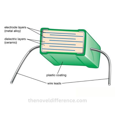
2. Capacitor Design: Dielectric Constant and Relative Permittivity Are Fundamental Parameters in the Design and Operation of Capacitors. These Components Store Electrical Energy by Utilizing a Dielectric Material Between Conductive Plates. the Dielectric Constant Determines the Capacitance Value and the Amount of Energy That Can Be Stored per Unit Volume. Different Materials With Varying Dielectric Constants Can Significantly Affect the Performance and Characteristics of capacitors.
3. Insulation Properties: Dielectric Constant and Relative Permittivity Are Crucial in Assessing the Insulation Properties of Materials. Materials With High Dielectric Constants Can Effectively Store and Distribute Electrical Charges, Making Them Suitable for Insulating Applications. Understanding These Parameters Helps in Selecting Appropriate Insulating Materials for Electrical Wiring, Cables, and Other Systems Where Electrical Isolation Is essential.
4. Wave Propagation: Dielectric Constant and Relative Permittivity Influence the Propagation of Electromagnetic Waves in Different Media. These Parameters Determine the Velocity and Behavior of Waves When They Pass Through Materials. for Example, in Optical Fibers Used for Telecommunications, the Choice of Materials With Specific Dielectric Constants Allows Efficient Transmission of Light signals.
5. Characterization of Materials: Dielectric Constant and Relative Permittivity Are Used to Characterize and Classify Materials Based on Their Electrical Properties. These Parameters Provide Valuable Information About a Material’s Polarizability, Its Response to an Electric Field, and Its Ability to Store Electrical Energy. Such Characterization Is Essential in Fields Like Materials Science, Electronics, and telecommunications.
6. Device Performance: Dielectric Constant and Relative Permittivity Impact the Performance of Various Electronic Devices. in Components Like Capacitors, Transistors, and Integrated Circuits, These Parameters Affect Factors Such as Signal Propagation, Charge Storage, Signal-to-Noise Ratios, and Overall Device Efficiency. Optimizing These Parameters Is Crucial for Achieving Desired Device Performance and reliability.
7. Signal Integrity: Dielectric Constant and Relative Permittivity Influence the Integrity and Quality of Electrical Signals. These Parameters Affect the Impedance Matching, Signal Reflection, and Signal Propagation Characteristics Within Transmission Lines and Printed Circuit Boards. Accurate Knowledge of These Parameters Helps in Designing and Optimizing Signal Paths for Minimal Signal Loss and distortion.
Understanding the Significance of Dielectric Constant and Relative Permittivity in Electromagnetism Enables Engineers, Scientists, and Researchers to Make Informed Decisions in Material Selection, Component Design, and System Optimization. These Parameters Form the Basis for Efficient and Reliable Electrical Systems and Facilitate Advancements in Fields Such as Electronics, Telecommunications, Energy Storage, and More.
Dielectric Constant
Dielectric Constant, Also Known as Relative Permittivity, Is a Fundamental Property of a Material That Characterizes Its Ability to Store Electrical Energy in an Electric Field. It Is Denoted by the Symbol εR or κ (kappa).
Here Are Some Key Points About the Dielectric constant:
1. Definition: The Dielectric Constant Is Defined as the Ratio of the Electric Flux Density (D) Produced in a Material to the Electric Field Strength (E) Applied to It. Mathematically, It Can Be Expressed as εR = D/E.
2. Comparison to Vacuum: The Dielectric Constant of a Vacuum Is Defined as Exactly 1. All Other Materials Have Dielectric Constants Greater Than 1. the Dielectric Constant of a Material Indicates How It Responds to an Electric Field Compared to the vacuum.
3. Polarization of the Material: When an Electric Field Is Applied to a Dielectric Material, Its Atoms or Molecules May Become Polarized. This Polarization Leads to the Alignment of Charges Within the Material, Which in Turn Affects the Overall Behavior of the Electric Field. the Dielectric Constant Quantifies the Extent of This Polarization and Its Impact on the Electric field.
4. Energy Storage: Dielectric Materials Have the Ability to Store Electrical Energy in the Form of Electrostatic Potential Energy. the Higher the Dielectric Constant, the Greater the Energy That Can Be Stored per Unit Volume. This Property Is Exploited in Various Applications Such as Capacitors, Where the Dielectric Material Is Placed Between Conductive Plates to Enhance Energy storage.
5. Influence on Electric Field: The Dielectric Constant Affects the Strength of the Electric Field Within a Material. in the Presence of a Dielectric, the Electric Field Strength Is Reduced Compared to the Applied Field Strength. the Degree of Reduction Depends on the Dielectric Constant of the Material. the Higher the Dielectric Constant, the More the Electric Field Is weakened.
6. Material Properties: Different Materials Have Different Dielectric Constants, Which Arise From Variations in Their Atomic or Molecular Structures. Materials Such as Ceramics, Plastics, Glass, and Certain Metals Exhibit Dielectric Behavior. the Dielectric Constant Can Vary Significantly Across Different Materials, Ranging From Very Low Values (e.g., Air) to Extremely High Values (e.g., Some ceramics).
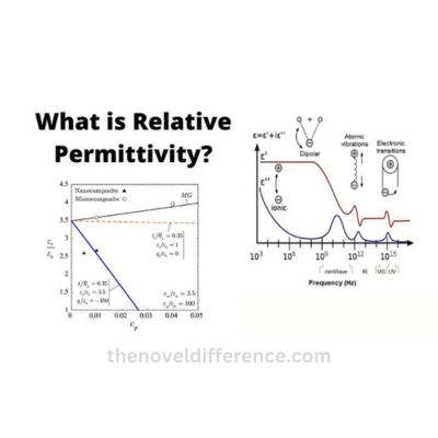
7. Frequency Dependence: The Dielectric Constant Can Vary With the Frequency of the Applied Electric Field. Materials That Exhibit Frequency-Dependent Dielectric Constants Are Called Dispersive Materials. This Frequency Dependence Is Often Described by a Complex Dielectric Constant That Includes Both Real and Imaginary components.
8. Measurement: The Dielectric Constant of a Material Can Be Determined Through Experimental Techniques Such as Capacitance Measurement, Resonant Methods, or Impedance Spectroscopy. These Methods Involve Measuring the Response of the Material to an Applied Electric Field Under Controlled conditions.
The Dielectric Constant Is a Vital Parameter in Understanding the Behavior of Materials in the Presence of Electric Fields. Its Knowledge Enables the Design and Optimization of Electrical Systems, the Selection of Appropriate Materials for Specific Applications, and the Development of Technologies in Areas Such as Electronics, Telecommunications, Energy Storage, and More.
Physical Interpretation of Dielectric constant
The Physical Interpretation of the Dielectric Constant Is Closely Tied to the Concept of Polarization in Dielectric Materials. When an Electric Field Is Applied to a Dielectric Material, Its Atoms or Molecules Undergo a Response Known as Polarization.
This Polarization Results in the Alignment of Charges Within the Material, Leading to Various Effects on the Electric field. The Dielectric Constant Quantifies the Extent of This Polarization and Provides Insights Into How a Material Responds to an Applied Electric Field Compared to a Vacuum.
Here Are Some Key Aspects of the Physical Interpretation of the Dielectric constant:
1. Induced Electric Field: When an External Electric Field Is Applied to a Dielectric Material, It Induces an Internal Electric Field Within the Material. This Induced Field Is in the Opposite Direction to the Applied Field and Weakens Its Overall Effect. the Dielectric Constant Determines the Magnitude of the Induced Electric field.
2. Polarization of Atoms or Molecules: The Dielectric Constant Reflects the Ability of a Material’s Atoms or Molecules to Become Polarized Under the Influence of an Electric Field. Polarization Occurs as the Positive and Negative Charges Within the Atoms or Molecules Are Displaced, Resulting in an Overall Dipole Moment. the Dielectric Constant Measures the Efficiency of This polarization.
3. Charge Separation and Redistribution: The Applied Electric Field Causes Charge Separation and Redistribution. Positive Charges Are Displaced in One Direction, While Negative Charges Are Displaced in the Opposite Direction. the Dielectric Constant Describes the Material’s Ability to Sustain This Charge Separation and redistribution.
4. Energy Storage: The Dielectric Constant Is Related to the Energy Storage Capability of a Dielectric Material. When an Electric Field Is Applied, the Polarization of the Material Allows It to Store Electrical Energy in the Form of Electrostatic Potential Energy. Materials With Higher Dielectric Constants Can Store More Energy per Unit volume.
5. Electric Field Strength Reduction: The Dielectric Constant Influences the Electric Field Strength Within a Dielectric Material. as the Electric Field Passes Through the Material, Its Strength Is Reduced Compared to the Applied Field. the Dielectric Constant Determines the Degree of Reduction, and Higher Values Correspond to Greater Weakening of the Electric field.
6. Screening Effect: Dielectric Materials Can Exhibit a Screening Effect Due to Their Ability to Polarize in Response to an Electric Field. This Screening Effect Reduces the Effective Electric Field Experienced by Charges Within the Material. the Dielectric Constant Characterizes the Effectiveness of This Screening process.
The Physical Interpretation of the Dielectric Constant Lies in Its Relation to Polarization Phenomena and the Material’s Response to an Applied Electric Field. It Describes the Ability of a Dielectric Material to Sustain Charge Separation, Redistribute Charges, Store Electrical Energy, and Weaken the Electric Field strength.
Understanding the Dielectric Constant Is Essential for Analyzing and Predicting the Behavior of Dielectric Materials in Various Applications, Including Capacitors, Insulators, and Electronic Devices.
Calculation and Measurement of Dielectric constant
The Dielectric Constant of a Material Can Be Determined Through Various Calculation and Measurement Techniques.
Here Are Some Common Methods Used for Calculating and Measuring the Dielectric constant:
1. Calculation From Material Properties:
A. Molecular Structure: The Dielectric Constant Can Be Estimated Based on the Molecular Structure of the Material. Theoretical Models and Empirical Relationships May Provide Approximations for Dielectric Constant Values Based on Molecular Properties Such as Polarizability and Dipole Moments.
B. Density Functional Theory (DFT): DFT Calculations Can Be Employed to Predict the Dielectric Constant of a Material by Simulating Its Electronic Structure and Polarization Response to an Electric Field. DFT Calculations Require Advanced Computational Methods and software.
2. Capacitance Measurement:
A. Parallel Plate Capacitor: One of the Most Common Methods for Measuring the Dielectric Constant Is Through the Use of a Parallel Plate Capacitor. the Capacitor Consists of Two Conductive Plates Separated by a Dielectric Material. by Measuring the Capacitance of the Capacitor With and Without the Dielectric, the Dielectric Constant Can Be Calculated Using the Formula: εR = C / (ε0 * a / D), Where εR Is the Dielectric Constant, C Is the Capacitance, ε0 Is the Vacuum Permittivity, a Is the Area of the Plates, and D Is the Distance Between the Plates.
B. Interdigitated Electrodes: Another Approach Is to Use Interdigitated Electrodes, Where Multiple Electrode Fingers Are Closely Spaced. the Sample Material Is Placed Between the Fingers, and the Capacitance Is Measured. the Dielectric Constant Can Be Calculated Using the Electrode Geometry and the Measured capacitance.
3. Resonant Methods:
A. Resonant Cavity Method: This Method Involves Placing a Sample Material Inside a Resonant Cavity and Measuring the Resonant Frequency. the Dielectric Constant Can Be Determined by Comparing the Resonant Frequency of the Sample Material With the Resonant Frequency of a Reference Material of Known Dielectric Constant.
B. Open-Ended Coaxial Probe: An Open-Ended Coaxial Probe Is Inserted Into the Sample Material. by Measuring the Changes in the Transmission Coefficient or the Reflection Coefficient of the Probe, the Dielectric Constant Can Be Calculated Using Calibration Data and Mathematical models.
4. Time Domain Reflectometry (TDR): TDR Is a Technique That Utilizes Pulses of Electromagnetic Waves to Measure the Dielectric Constant of Materials. the Propagation Time of the Pulse Through the Material Is Measured and Compared to the Propagation Time in a Reference Material. by Analyzing the Time Delay, the Dielectric Constant Can Be determined.
5. Impedance Spectroscopy: Impedance Spectroscopy Involves Measuring the Impedance of a Material as a Function of Frequency. by Analyzing the Complex Impedance and Fitting It to Appropriate Models, the Dielectric Constant Can Be Extracted for Different frequencies.
It’s Important to Note That the Specific Method Used for Calculating or Measuring the Dielectric Constant Depends on Factors Such as the Nature of the Material, the Desired Accuracy, and the Available equipment.
Some Methods May Be More Suitable for Solid Materials, While Others May Be Better for Liquids or Gases. the Dielectric Constant Can Also Vary With Frequency, Temperature, and Other Factors, So It’s Crucial to Consider These Parameters When Performing Calculations or Measurements.
Relative Permittivity
Relative Permittivity, Also Known as the Dielectric Constant, Is a Fundamental Property of a Material That Quantifies Its Ability to Store Electrical Energy in an Electric Field Compared to a Vacuum. It Is Denoted by the Symbol εr.
Here Are Some Key Points About Relative permittivity:
1. Definition: Relative Permittivity Is Defined as the Ratio of the Permittivity of a Material (ε) to the Permittivity of Free Space (ε0). Mathematically, It Can Be Expressed as εR = ε/ε0.
2. Comparison to Vacuum: The Relative Permittivity of a Vacuum Is Defined as Exactly 1. Materials With Relative Permittivity Greater Than 1 Are Called Dielectric Materials and Exhibit the Ability to Store Electrical energy.
3. Polarizability: Relative Permittivity Is Closely Related to the Polarizability of a Material. When an Electric Field Is Applied, the Atoms or Molecules in the Material Undergo Polarization, Resulting in the Alignment of Charges. the Relative Permittivity Quantifies the Efficiency of This Polarization process.
4. Influence on Electric Field: The Presence of a Dielectric Material With a Relative Permittivity Greater Than 1 Alters the Electric Field Within It. It Weakens the Electric Field Strength Compared to the Applied Field Strength. the Extent of This Weakening Depends on the Relative Permittivity of the material.
5. Capacitance Calculation: Relative Permittivity Plays a Significant Role in the Calculation of Capacitance. the Capacitance of a Capacitor Is Directly Proportional to the Relative Permittivity of the Dielectric Material Placed Between the Capacitor Plates. a Higher Relative Permittivity Results in a Larger Capacitance, Indicating the Ability to Store More Electrical charge.
6. Energy Storage: Relative Permittivity Is Related to the Energy Storage Capability of a Dielectric Material. It Determines the Amount of Electrical Energy That Can Be Stored per Unit Volume. Materials With Higher Relative Permittivity Can Store More Energy in an Electric field.
7. Frequency Dependence: Relative Permittivity Can Vary With the Frequency of the Applied Electric Field. Some Materials Exhibit Frequency-Dependent Relative Permittivity, Known as Dispersion. the Variation of Relative Permittivity With Frequency Is Important in Understanding the Behavior of Materials in Different Electromagnetic applications.
8. Material Properties: Different Materials Have Different Relative Permittivity Values, Which Arise From Variations in Their Atomic or Molecular Structures. Materials Such as Ceramics, Plastics, Glass, and Certain Metals Exhibit Dielectric Behavior and Possess Varying Relative Permittivity values.
9. Measurement: The Relative Permittivity of a Material Can Be Measured Using Techniques Such as Capacitance Measurement, Impedance Spectroscopy, or Resonant Methods. These Methods Involve Analyzing the Electrical Response of the Material to an Applied Electric Field or Varying frequencies.
Relative Permittivity Is a Crucial Parameter in Understanding the Behavior of Dielectric Materials and Their Interactions With Electric Fields. It Has Significant Implications in Various Fields Such as Electronics, Telecommunications, Energy Storage, and Material science. The Knowledge of Relative Permittivity Allows for the Design and Optimization of Electrical Systems and the Selection of Appropriate Materials for Specific Applications.
Concept of Permittivity and Its Role in Electric fields
Permittivity Is a Fundamental Property of a Material That Characterizes Its Ability to Store Electrical Energy in an Electric Field. It Plays a Crucial Role in Understanding and Analyzing the Behavior of Electric fields.
Here Are Key Points About Permittivity and Its Role in Electric fields:
1. Definition: Permittivity Is a Measure of a Material’s Ability to Permit the Formation of an Electric Field Within It When Subjected to an Applied Electric Field. It Quantifies How Much Electric Flux Density (D) Is Generated in Response to an Electric Field Strength (E). Permittivity Is Denoted by the Symbol ε.
2. Relation to Electric Field: Permittivity Relates the Electric Field Strength (E) and the Electric Flux Density (D) Through the Equation D = εE. It Defines How the Electric Field Interacts With a Material and Determines the Strength and Behavior of the Resulting Electric Field Within the material.
3. Different Types of Permittivity:
A. Vacuum Permittivity: Vacuum Permittivity, Denoted as ε0 (Epsilon Zero), Represents the Permittivity of Free Space. It Is a Fundamental Constant With a Fixed Value.
B. Relative Permittivity: Relative Permittivity, Also Known as the Dielectric Constant, Is the Ratio of the Permittivity of a Material (ε) to the Vacuum Permittivity (ε0). It Quantifies a Material’s Ability to Store Electrical Energy Relative to Free Space. Materials With Relative Permittivity Greater Than 1 Are Called Dielectric materials.
4. Influence on Electric Field Strength: Permittivity Affects the Strength of the Electric Field Within a Material. the Higher the Permittivity, the More the Electric Field Is Weakened or Reduced Within the Material Compared to the Applied Field Strength. This Effect Is Crucial in Applications Such as Insulation, Capacitors, and Wave propagation.
5. Energy Storage: Permittivity Is Directly Related to the Energy Storage Capability of a Material. It Determines How Much Electrical Energy Can Be Stored per Unit Volume Within the Material When an Electric Field Is Applied. Materials With Higher Permittivity Can Store More Electrical Energy, Making Them Suitable for Applications Such as capacitors.
6. Polarization: Permittivity Is Closely Linked to the Polarization of a Material in an Electric Field. When an Electric Field Is Applied, the Atoms or Molecules Within the Material Undergo Polarization, Resulting in the Alignment of Charges. This Polarization Response Contributes to the Permittivity of the material.
7. Frequency Dependence: Permittivity Can Vary With the Frequency of the Applied Electric Field. Some Materials Exhibit Frequency-Dependent Permittivity, Known as Dispersion. This Frequency Dependence Is Particularly Significant in Applications Involving Varying Frequencies, Such as Telecommunications and Electromagnetic Wave propagation.
8. Electric Field Behavior in Materials: Permittivity Determines How an Electric Field Behaves Within a Material. It Affects Factors Such as Electric Field Strength, Electric Flux Density, Charge Storage, and Propagation Velocity. Understanding the Permittivity of Materials Is Essential for Designing and Optimizing Electrical Systems, Choosing Appropriate Insulating Materials, and Predicting the Behavior of Electromagnetic waves.
Permittivity Plays a Fundamental Role in Describing the Interaction Between Electric Fields and Materials. It Provides Valuable Insights Into the Behavior of Electric Fields Within Dielectric Materials, Enabling the Design and Analysis of Various Electrical and Electronic Devices, Communication Systems, and Energy Storage Technologies.
Calculation and Measurement of Relative permittivity
The Relative Permittivity, Also Known as the Dielectric Constant, of a Material Can Be Calculated or Measured Using Various Techniques.
Here Are Some Common Methods for Calculating and Measuring Relative permittivity:
1. Calculation From Material Properties:
• Molecular Structure: The Relative Permittivity Can Be Estimated Based on the Molecular Structure of the Material. Theoretical Models and Empirical Relationships May Provide Approximations for Relative Permittivity Values Based on Molecular Properties Such as Polarizability and Dipole moments.
• Density Functional Theory (DFT): DFT Calculations Can Be Employed to Predict the Relative Permittivity of a Material by Simulating Its Electronic Structure and Polarization Response to an Electric Field. DFT Calculations Require Advanced Computational Methods and software.
2. Capacitance Measurement:
• Parallel Plate Capacitor: One of the Most Common Methods for Measuring Relative Permittivity Is Through the Use of a Parallel Plate Capacitor. the Capacitor Consists of Two Conductive Plates Separated by the Material Whose Relative Permittivity Is to Be Determined. by Measuring the Capacitance of the Capacitor, the Relative Permittivity Can Be Calculated Using the Formula: εR = C / (ε0 * a / D), Where εR Is the Relative Permittivity, C Is the Capacitance, ε0 Is the Vacuum Permittivity, a Is the Area of the Plates, and D Is the Distance Between the plates.
3. Resonant Methods:
• Resonant Cavity Method: This Method Involves Placing a Sample Material Inside a Resonant Cavity and Measuring the Resonant Frequency. the Relative Permittivity Can Be Determined by Comparing the Resonant Frequency of the Sample Material With the Resonant Frequency of a Reference Material of Known Relative permittivity.
• Open-Ended Coaxial Probe: An Open-Ended Coaxial Probe Is Inserted Into the Sample Material. by Measuring the Changes in the Transmission Coefficient or the Reflection Coefficient of the Probe, the Relative Permittivity Can Be Calculated Using Calibration Data and Mathematical models.
4. Time Domain Reflectometry (TDR): TDR Is a Technique That Utilizes Pulses of Electromagnetic Waves to Measure the Relative Permittivity of Materials. the Propagation Time of the Pulse Through the Material Is Measured and Compared to the Propagation Time in a Reference Material. by Analyzing the Time Delay, the Relative Permittivity Can Be determined.
5. Impedance Spectroscopy: Impedance Spectroscopy Involves Measuring the Impedance of a Material as a Function of Frequency. by Analyzing the Complex Impedance and Fitting It to Appropriate Models, the Relative Permittivity Can Be Extracted for Different frequencies.
6. Interferometric Techniques: Interferometric Techniques, Such as Fabry-Perot Interferometry or Mach-Zehnder Interferometry, Can Be Used to Measure the Refractive Index of a Material. by Knowing the Refractive Index, the Relative Permittivity Can Be Determined Using the Relationship εR = N^2, Where N Is the Refractive index.
It’s Important to Note That the Specific Method Used for Calculating or Measuring Relative Permittivity Depends on Factors Such as the Nature of the Material, the Desired Accuracy, and the Available equipment.
Some Methods May Be More Suitable for Solid Materials, While Others May Be Better for Liquids or Gases. Additionally, the Relative Permittivity Can Also Vary With Frequency, Temperature, and Other Factors, So It’s Crucial to Consider These Parameters When Performing Calculations or Measurements.
Difference Between Dielectric Constant and Relative Permittivity
The Terms “Dielectric Constant” and “Relative Permittivity” Are Often Used Interchangeably, but They Have Slightly Different Meanings and Contexts.
Here Are the Key Differences Between Dielectric Constant and Relative permittivity:
1. Definition:
• Dielectric Constant: Dielectric Constant Refers to the Same Concept as Relative Permittivity, but It Is an Older Term That Is Still Commonly Used. It Represents the Ability of a Material to Store Electrical Energy in an Electric Field Relative to the Ability of a Vacuum to Store Electrical energy.
• Relative Permittivity: Relative Permittivity Is a More Modern and Preferred Term for the Same Concept. It Is Defined as the Ratio of the Permittivity of a Material (ε) to the Permittivity of Free Space (ε0).
2. Quantitative Value:
• Dielectric Constant: The Dielectric Constant Is a Dimensionless Quantity, and Its Value Represents the Ratio of the Capacitance of a Capacitor With a Specific Material as the Dielectric Compared to a Capacitor With a Vacuum as the Dielectric. for Example, a Dielectric Constant of 3 Means the Capacitance Is Three Times Larger With the Given Material Compared to a vacuum.
• Relative Permittivity: The Relative Permittivity Is Also a Dimensionless Quantity, and Its Value Represents the Ratio of the Permittivity of a Material to the Permittivity of Free Space. It Indicates How Many Times the Electric Field Is Weakened or Reduced Within the Material Compared to Free space.
3. Usage:
• Dielectric Constant: The Term “Dielectric Constant” Is More Commonly Used in Older Literature or in Informal discussions.
• Relative Permittivity: The Term “Relative Permittivity” Is More Commonly Used in Modern Scientific and Engineering contexts.
4. Symbol:
• Dielectric Constant: The Symbol for the Dielectric Constant Is Typically ε or εR (Epsilon Sub r).
• Relative Permittivity: The Symbol for Relative Permittivity Is εR (Epsilon Sub R) or Simply ε.
Despite These Differences in Terminology and Usage, the Concepts of Dielectric Constant and Relative Permittivity Represent the Same Fundamental Property of a Material’s Ability to Store Electrical Energy in an Electric Field. Both Terms Are Used to Describe the Same Property and Are Interchangeable in Most Practical situations.
Conclusion
The Difference Between Dielectric Constant and Relative Permittivity Lies in Their Definitions, Units, and Applications. While Dielectric Constant Is an Absolute Quantity, Relative Permittivity Is a Dimensionless ratio.
Dielectric Constant Is Used to Determine the Capacitance of a Material, While Relative Permittivity Is Used to Describe How a Material Affects the Electric Field Inside it.
Understanding the Differences Between These Two Terms Is Essential for Designing Electronic Circuits, Predicting the Behavior of Materials in Electrical Fields, and Studying Various Physical and Chemical phenomena.